-
Hey Guest one of our sponsors Progressive Parts is running Black Friday and Cyber Monday offers - more details here
Home Made IC Spray System
- Thread starter cupra_matt
- Start date
You are using an out of date browser. It may not display this or other websites correctly.
You should upgrade or use an alternative browser.
You should upgrade or use an alternative browser.
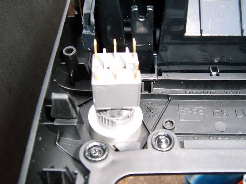
need part no for the pump and im going to use a pressure switch to run the system with a switch hidden in the car to power the hole thing
Part nuber for the pump is 3B7 955 681 you will also need the gromet it sits in which is 431 955 465A and the connecting peice to join the pipe on which is 8D0 955 875
cheers mate got a ruff idea how much it all costs because ive got the pressure switch i need to run it all and where did you get the jets from if you dont mind all the questions
flash, you ever seen a set of valves from a car after it has been running auqamist?
Not a pretty sight, steel and water dont go well 2gether
Not a pretty sight, steel and water dont go well 2gether
Surely the heat of the engine, mixed with the oil means that there will be no standing water in the engine and that parts will have been re-coated in oil anyway??
Never heard anyone else have problems with aqua mist eating valves before??
Never heard anyone else have problems with aqua mist eating valves before??
flash, you ever seen a set of valves from a car after it has been running auqamist?
Not a pretty sight, steel and water dont go well 2gether
They do if its stainless which i'm sure they will be...???

JAmes
Nearly finished, haven't had time though due to putting clutch in it and removing the head to sort blowing exhaust manifold.. Should get it done this week.
Finally got it finished.
GUIDE
Parts required:
1. Headlight washer pump for 6K Ibiza 3B7 955 681
2. Grommet which the pump sits in. 431 955 465A
3.Connector to connect pipe to pump 8D0 955 875
4. Ibiza Washer Jets or spray bar ( Ibiza Jets 6E0 955 985B)
5. Some 6mm ( i think ) water pipe 2 - 3 metres should cover it.
6. 6mm T Peice ( havent got the number for this, but its on the same ETKA screen as the pump.
7. Some smaller pipe approx 3mm for anti syphon.
8. Some sort of switch to activate the system, Here is mine. http://cgi.ebay.co.uk/ws/eBayISAPI.dll?ViewItem&category=72218&item=300020088105
9. Wire and connectors.
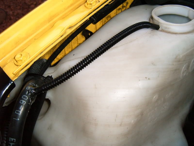
I started by drilling the washer bottle using a cone cutter. Dont go too big or your screwed, go big enough so that the grommet is a nice snug fit. Then press the motor into the bottle.
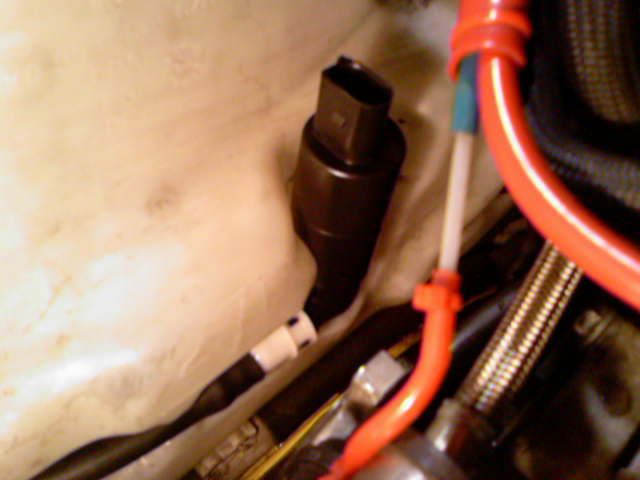
Now you need to remove your front bumper. Once removed get your 6mm pipe and connect one end to the connection peice and push it on the pump. Now run the pipe through the small gap under the drivers headlight and take it to the corner of the intercooler, this is where you need to put the T piece. Make sure at some point the pipe is as high as you can get it in the engine bay to help stop it syhoning out.
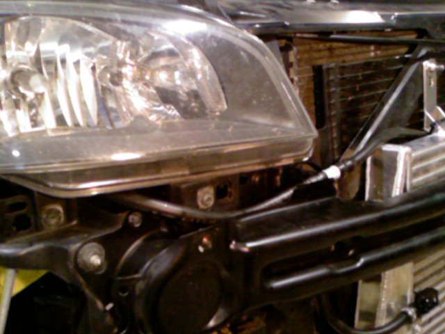
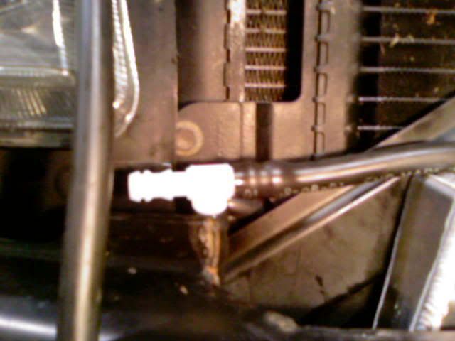
Now mount the jets on the intercooler. I chose to attach them with tiny cable ties going round one of the cores of the intercooler. Now run pipe from your T peice to the Jets and secure the pipes in place so they dont move. Fit jubilee clips on all connections as the headlight washer pump is quite powerful and might blow the pipe off. Refit the bumper.
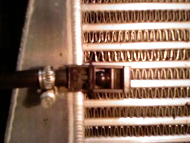
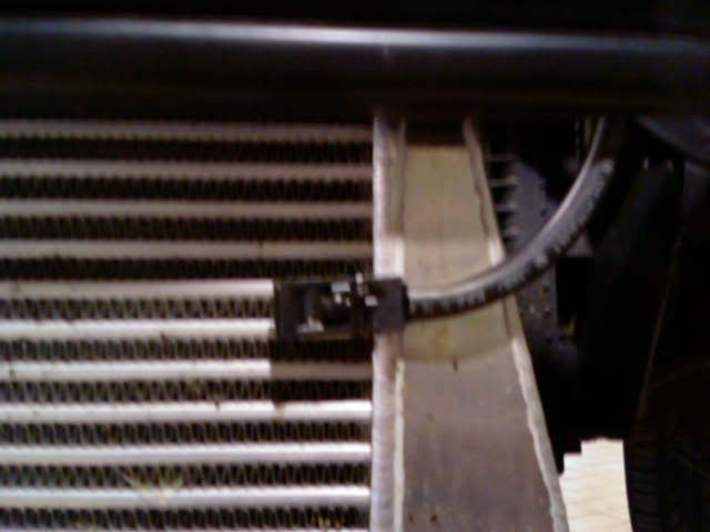
Now at the highest point of your pipe you need to drill a small hole in the pipe and feed the smaller 3mm pipe into it, then drill a small hole in the top of your washer bottle and feed the other end into there. Or you can use a T peice ( this is the only way i could get it to stop syhoning out. I did try valves etc but none worked, This does).
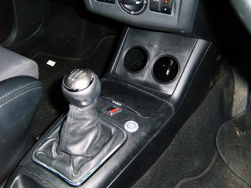
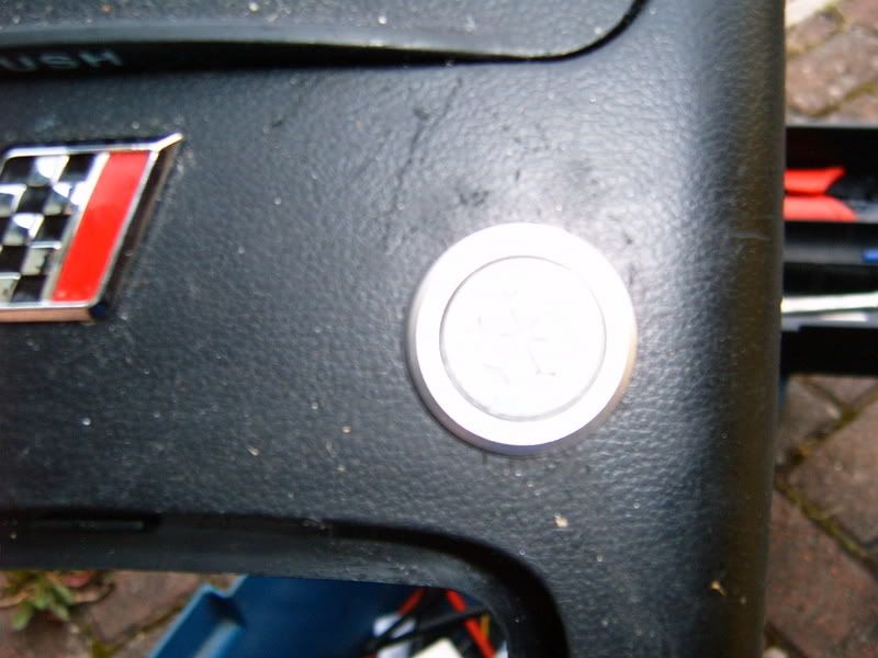
Now onto wiring. This is fairly simple and may vary depending on the type of switch you go for. Mine is a push button with illumination designed for Aircon system, ( it works).
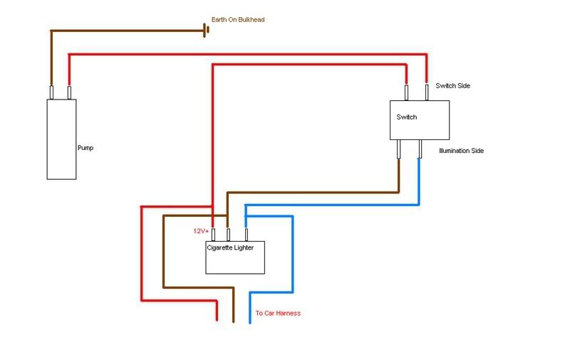
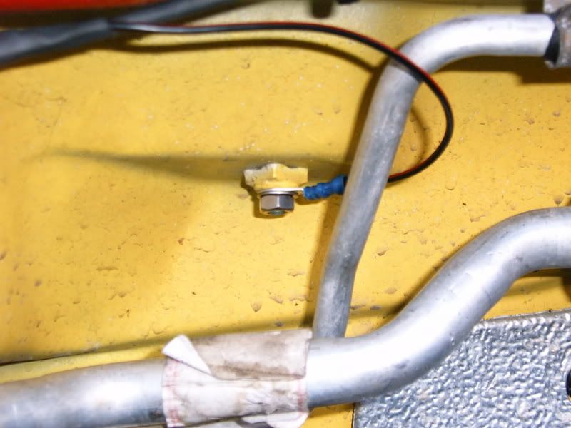
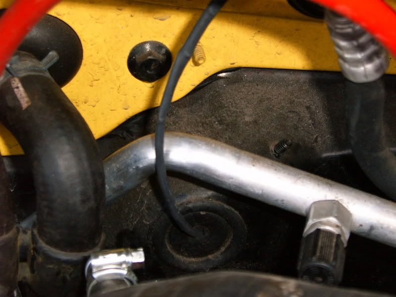
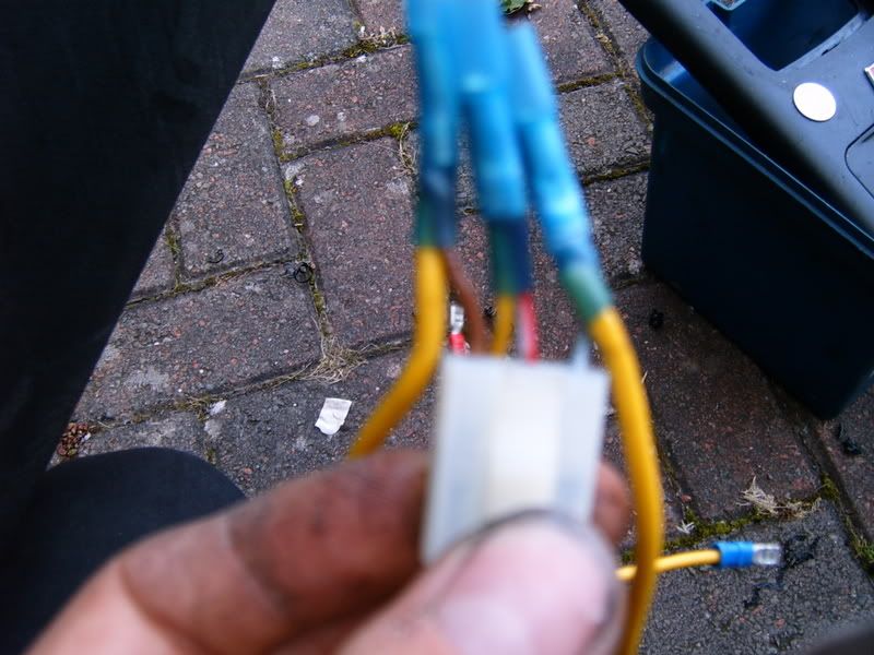
The pump is a 2 pin connection and needs a 12V feed and and an earth.
For the earth i used the bolt that comes through the bulkhead and simply put a connector with a nut on it. See PIC. Your one remaining pin is your live.
Take the wire and route it to your preference ( mine is attached to my strut brace) and take it to the grommet near the aircon pipe on the bulkhead and feed it through there.
Remove the trim panel in the passenger footwell under the glove box and you should see the cable. Feed the cable to where ever you mount your switch. ( mines next to ash tray) Because of my switches location i used the cigarette lighter as my power source as it is heavy duty and already fused.
There are 3 wires to the cigarette lighter.
Red/Black (iirc) 12+
Brown Earth
Light blue Illumination
Simply tap into the 12+ for your feed and connect it too one side of your switch and then connect the other cable which you fed through the bulkhead to the other side of the switch and hey presto.
If your switch is illuminated then use the light blue wire as your illumination feed and the brown as earth, this circuit is also fused and hence safe too use.
Hope this helps
GUIDE
Parts required:
1. Headlight washer pump for 6K Ibiza 3B7 955 681
2. Grommet which the pump sits in. 431 955 465A
3.Connector to connect pipe to pump 8D0 955 875
4. Ibiza Washer Jets or spray bar ( Ibiza Jets 6E0 955 985B)
5. Some 6mm ( i think ) water pipe 2 - 3 metres should cover it.
6. 6mm T Peice ( havent got the number for this, but its on the same ETKA screen as the pump.
7. Some smaller pipe approx 3mm for anti syphon.
8. Some sort of switch to activate the system, Here is mine. http://cgi.ebay.co.uk/ws/eBayISAPI.dll?ViewItem&category=72218&item=300020088105
9. Wire and connectors.
I started by drilling the washer bottle using a cone cutter. Dont go too big or your screwed, go big enough so that the grommet is a nice snug fit. Then press the motor into the bottle.

Now you need to remove your front bumper. Once removed get your 6mm pipe and connect one end to the connection peice and push it on the pump. Now run the pipe through the small gap under the drivers headlight and take it to the corner of the intercooler, this is where you need to put the T piece. Make sure at some point the pipe is as high as you can get it in the engine bay to help stop it syhoning out.


Now mount the jets on the intercooler. I chose to attach them with tiny cable ties going round one of the cores of the intercooler. Now run pipe from your T peice to the Jets and secure the pipes in place so they dont move. Fit jubilee clips on all connections as the headlight washer pump is quite powerful and might blow the pipe off. Refit the bumper.


Now at the highest point of your pipe you need to drill a small hole in the pipe and feed the smaller 3mm pipe into it, then drill a small hole in the top of your washer bottle and feed the other end into there. Or you can use a T peice ( this is the only way i could get it to stop syhoning out. I did try valves etc but none worked, This does).

Now onto wiring. This is fairly simple and may vary depending on the type of switch you go for. Mine is a push button with illumination designed for Aircon system, ( it works).


The pump is a 2 pin connection and needs a 12V feed and and an earth.
For the earth i used the bolt that comes through the bulkhead and simply put a connector with a nut on it. See PIC. Your one remaining pin is your live.
Take the wire and route it to your preference ( mine is attached to my strut brace) and take it to the grommet near the aircon pipe on the bulkhead and feed it through there.
Remove the trim panel in the passenger footwell under the glove box and you should see the cable. Feed the cable to where ever you mount your switch. ( mines next to ash tray) Because of my switches location i used the cigarette lighter as my power source as it is heavy duty and already fused.
There are 3 wires to the cigarette lighter.
Red/Black (iirc) 12+
Brown Earth
Light blue Illumination
Simply tap into the 12+ for your feed and connect it too one side of your switch and then connect the other cable which you fed through the bulkhead to the other side of the switch and hey presto.
If your switch is illuminated then use the light blue wire as your illumination feed and the brown as earth, this circuit is also fused and hence safe too use.
Hope this helps
Last edited:
and i was thinking of using a boost switch like this http://cgi.ebay.co.uk/Boost-Switche...ryZ72205QQssPageNameZWD1VQQrdZ1QQcmdZViewItem so it isnt spraying all the time and only when you hit say 10psi
Similar threads
- Replies
- 2
- Views
- 282
- Replies
- 0
- Views
- 129
- Replies
- 14
- Views
- 2K
- Replies
- 0
- Views
- 134


