-
Hey Guest - Would you be interested in branded CUPRA or SEAT number plates for your car? 👉 Check out the designs and register your interest now
Blind spot detection
- Thread starter Kate1304
- Start date
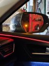
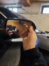
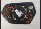
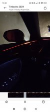
I take a picture with second hole for test. We have 3 options. I choose Door panel
Attachments
-
 IMG_20240306_195609.jpg413.5 KB · Views: 202
 -
 IMG_20240308_164031.jpg382.7 KB · Views: 177
 -
 IMG_20240308_072311.jpg83.2 KB · Views: 179
 -
 Screenshot_2024-03-07-19-42-39-771_com.miui.videoplayer.jpg109.9 KB · Views: 181
")
I chose the door. Unfortunately, it doesn't go higher than the original. it is too built up. there is no place to fit this LED module there. maybe one day, when I have some spare cash, I will buy original door panels. now there will be an action to open the trunk lid electrically.
Soon I am going to add side assist for my cupra Leon ST. I will show result, all cost and coding.
I have ordered original door panels with the lights and side assist set from kufatec.
I have ordered original door panels with the lights and side assist set from kufatec.
I got it activated and removed Component Protection and tested it all on the car off @mysticscalex today.
Works like a charme
Works like a charme
IMPORTANT: This is not just Plug and Play. Travel assist not necessary to have installed, but recommended to. Automatic lane change possible, but Camera software needs to be up-to-date and correct part number. Also need to have parking sensor frond and back.
As promised, following I will give instruction of installation, costs and coding. This is for Sportstourer, but hatchback is almost the same.
Install:
1. Remove the rear bumper and interior panel right side:
-take out rear light, screws are behind cover
-remove all 8 screws from wheel arch left and right
-Remove underside screws (6x) and 2x plastic clip
-Remove 2x screw under rear light
-Remove panel by undoing screws (or push is slightly aside to get between it)
-remove bumper and attach radars and cable to the chassis, then run the cable through the rubber grommet.
2. Run the cable from right rear of car to right front:
-pull the cable with a cable puller underneath all the interior panels or remove them.
3. Doorpanel removal and cable installation:
-Remove door panel by taking off the handels and switch, then remove 2 screw and take it off.
-Remove speaker and take the cable set for the light and pull it through the rubber grommets and insert the wires in the door connector. Lin wire (Red wire in the lamp) goes in Pin 13 of connector. Ground in pin 14.
-Swap all components over to the new door panels
4. Cable routing to left side and installation:
-Take the ground wire and the 2 wires for the lamp of the right side and attach these. (Make sure you match the LIN wire and Ground wire of the lamp accordingly in the door connector)
-Take the rest (left side lamp wires, CAN high and low, Fuse wire) to the left side of the car.
-route the cables how you like, but do check that you have enough cable left to insert it and tuck it away properly. (I routed mine underneath the carpet, across the transmission tunnel.)
-once it sits properly, plug in the wires for the lamp in the door connector (make sure the wire from the radar Pin 6 (LIN wire) goes in Pin 13 door connector)
-use a wire connector and take the can High and Can low and attach these to the existing wire on the cambus gateway. If you use the gateway directly, it will be Can High Pin 7 (Gray cable) and Can Low Pin 6 (Orange/Brown).
-you can also use the black connector at the hood release, this also has the Can high and Can Low wires, but in the connector they are on Pin 12 and Pin 13 (Pin 12 Can High, Pin 13 Can Low)
-Side Assist CAN is an extension to the existing CAN network, so make sure the connection to the wires is good. You can use an item where you tap into the wire, or just strip the wire of insulation and wrap the other wire around it and then solder it together.
-After this is all done, pull out the fuse box left of steering column and remove the blocking pin, then insert Fuse wire. This part can be tricky, but try and wriggle around the box so you can see the back side and have enough space to insert the wire.
5. Coding and CP removal:
-You have now installed all the components, now you need to do some coding and remove the Component Protection. Coding can be done with dongle from Kufatec, or using OBD11. CP removal needs to be done with ODIS or a tool that gives access to VW servers.
coding is as follows: (credit to Niky89 on another forum)
1) GATEWAY
Register 3C modules
2) Control unit: 03 Brakes (ABS)
Long coding:
Byte 18 activate bit 3 (already ON in my car)
Byte 30 activate bit 4 (already ON in my car)
Adaptations:
-Delay management:
Rear cross traffic assistant: Not activated --> Activated
3) Control unit: 17 Dashboard
Long coding:
Lane change assistance: No --> Yes
Lane change assistant, BAP distance: No --> YES
Lane retention assistant, BAP distance: No --> YES
Lane_change_assistent: no —> yes
Blind_spot_detection: no —> yes
4) Control unit: 5F Multimedia
Adaptations:
-Vehicle function list BAP:
SWA_0x1A: Not activated --> Activated
SWA_0x1A_msg_bus: Not activated --> Terminal 15
-Vehicle menu operation:
menu_display_lane_assistant: Not activated --> Activated
menu_display_lane_assistant_over_threshold_high: Not activated --> Activated
5) Control unit: A5 Driver Assistance
Long coding:
SWA: Not_coded --> Coded
blind_spot_detection: Not_coded --> Coded
HC_Mob_line: Not_coded —> Coded (this is for automatic lane change)
HC_var(this is for automatic lane change)
6) Control unit: 19 Gateway
Long coding:
PaCo_Rear_Cross_Traffic_Alest: not installed --> installed
7) Control unit: 75 Telematics
Adaptations:
-Vehicle function list BAP:
Lane change assistance: Not activated --> Activated
SWA_0x1A: Not activated —> activ
8) Control Unit: 44 steering assistance
Adaptions:
Qfk_ma_function: Not_active —> Active (this is for automatic lane change)
9) Control Unit: 13 ACC
Long Coding:
Lane_change_support: not activated —> activated
After the coding, Get the CP removed. Dealer can do this, but won’t because they don’t like, otherwise find someone who has equipment.
Finally, the cost:
740€ - Doorpanels (Bought via Dealer)
660€ - Kufatec set (Radars, Bracket, Cables, coding dongle)
110€ - OBD11
75€ - CP removal
5€ - Zipties, connector and tape
——— total
1590€ (this can very depending on country and shipping cost)
If you let someone do this for you, expect more than 2000€ for this retrofit.
Last but not least, I made schematic which shows which wires go where, and component numbers. Kufatec set I bought: (includes installation https://kufatec.com/en/lane-change-assistant-incl.-rear-traffic-allert-for-seat-leon-kl/45285

For my car, the left side already had the cable in the door for the light, but the pins were as original, unlike Kufatec set where the LIN wire left lamp is supposed to go into Pin 14 of door connector. In my case however Wire 14 had to be placed into Pin 13 of door connector.
here an foto of the Kufatec set, but you can also buy components yourself and make your own cables, whatever you find easier and more fun.

And as last, a photo of original Side assist lamp and cable in left doorpanel.

I forgot to make photos of installation in car, but it’s mostly straightforward and if you are an mechanic or have lots of experience disassembling interior than this shouldn’t be hard. Expect to be busy between 6 to 8 hours max.
After everything is done, made a calibration test drive (goes automatically) and it correctly detects overtaking traffic or traffic driving beside you. Have not yet experienced an alert when driving out a parking spot or when opening door when traffic is coming, but this will also work.
if you have any questions, send me a PM.
As promised, following I will give instruction of installation, costs and coding. This is for Sportstourer, but hatchback is almost the same.
Install:
1. Remove the rear bumper and interior panel right side:
-take out rear light, screws are behind cover
-remove all 8 screws from wheel arch left and right
-Remove underside screws (6x) and 2x plastic clip
-Remove 2x screw under rear light
-Remove panel by undoing screws (or push is slightly aside to get between it)
-remove bumper and attach radars and cable to the chassis, then run the cable through the rubber grommet.
2. Run the cable from right rear of car to right front:
-pull the cable with a cable puller underneath all the interior panels or remove them.
3. Doorpanel removal and cable installation:
-Remove door panel by taking off the handels and switch, then remove 2 screw and take it off.
-Remove speaker and take the cable set for the light and pull it through the rubber grommets and insert the wires in the door connector. Lin wire (Red wire in the lamp) goes in Pin 13 of connector. Ground in pin 14.
-Swap all components over to the new door panels
4. Cable routing to left side and installation:
-Take the ground wire and the 2 wires for the lamp of the right side and attach these. (Make sure you match the LIN wire and Ground wire of the lamp accordingly in the door connector)
-Take the rest (left side lamp wires, CAN high and low, Fuse wire) to the left side of the car.
-route the cables how you like, but do check that you have enough cable left to insert it and tuck it away properly. (I routed mine underneath the carpet, across the transmission tunnel.)
-once it sits properly, plug in the wires for the lamp in the door connector (make sure the wire from the radar Pin 6 (LIN wire) goes in Pin 13 door connector)
-use a wire connector and take the can High and Can low and attach these to the existing wire on the cambus gateway. If you use the gateway directly, it will be Can High Pin 7 (Gray cable) and Can Low Pin 6 (Orange/Brown).
-you can also use the black connector at the hood release, this also has the Can high and Can Low wires, but in the connector they are on Pin 12 and Pin 13 (Pin 12 Can High, Pin 13 Can Low)
-Side Assist CAN is an extension to the existing CAN network, so make sure the connection to the wires is good. You can use an item where you tap into the wire, or just strip the wire of insulation and wrap the other wire around it and then solder it together.
-After this is all done, pull out the fuse box left of steering column and remove the blocking pin, then insert Fuse wire. This part can be tricky, but try and wriggle around the box so you can see the back side and have enough space to insert the wire.
5. Coding and CP removal:
-You have now installed all the components, now you need to do some coding and remove the Component Protection. Coding can be done with dongle from Kufatec, or using OBD11. CP removal needs to be done with ODIS or a tool that gives access to VW servers.
coding is as follows: (credit to Niky89 on another forum)
1) GATEWAY
Register 3C modules
2) Control unit: 03 Brakes (ABS)
Long coding:
Byte 18 activate bit 3 (already ON in my car)
Byte 30 activate bit 4 (already ON in my car)
Adaptations:
-Delay management:
Rear cross traffic assistant: Not activated --> Activated
3) Control unit: 17 Dashboard
Long coding:
Lane change assistance: No --> Yes
Lane change assistant, BAP distance: No --> YES
Lane retention assistant, BAP distance: No --> YES
Lane_change_assistent: no —> yes
Blind_spot_detection: no —> yes
4) Control unit: 5F Multimedia
Adaptations:
-Vehicle function list BAP:
SWA_0x1A: Not activated --> Activated
SWA_0x1A_msg_bus: Not activated --> Terminal 15
-Vehicle menu operation:
menu_display_lane_assistant: Not activated --> Activated
menu_display_lane_assistant_over_threshold_high: Not activated --> Activated
5) Control unit: A5 Driver Assistance
Long coding:
SWA: Not_coded --> Coded
blind_spot_detection: Not_coded --> Coded
HC_Mob_line: Not_coded —> Coded (this is for automatic lane change)
HC_var(this is for automatic lane change)
6) Control unit: 19 Gateway
Long coding:
PaCo_Rear_Cross_Traffic_Alest: not installed --> installed
7) Control unit: 75 Telematics
Adaptations:
-Vehicle function list BAP:
Lane change assistance: Not activated --> Activated
SWA_0x1A: Not activated —> activ
8) Control Unit: 44 steering assistance
Adaptions:
Qfk_ma_function: Not_active —> Active (this is for automatic lane change)
9) Control Unit: 13 ACC
Long Coding:
Lane_change_support: not activated —> activated
After the coding, Get the CP removed. Dealer can do this, but won’t because they don’t like, otherwise find someone who has equipment.
Finally, the cost:
740€ - Doorpanels (Bought via Dealer)
660€ - Kufatec set (Radars, Bracket, Cables, coding dongle)
110€ - OBD11
75€ - CP removal
5€ - Zipties, connector and tape
——— total
1590€ (this can very depending on country and shipping cost)
If you let someone do this for you, expect more than 2000€ for this retrofit.
Last but not least, I made schematic which shows which wires go where, and component numbers. Kufatec set I bought: (includes installation https://kufatec.com/en/lane-change-assistant-incl.-rear-traffic-allert-for-seat-leon-kl/45285
For my car, the left side already had the cable in the door for the light, but the pins were as original, unlike Kufatec set where the LIN wire left lamp is supposed to go into Pin 14 of door connector. In my case however Wire 14 had to be placed into Pin 13 of door connector.
here an foto of the Kufatec set, but you can also buy components yourself and make your own cables, whatever you find easier and more fun.
And as last, a photo of original Side assist lamp and cable in left doorpanel.
I forgot to make photos of installation in car, but it’s mostly straightforward and if you are an mechanic or have lots of experience disassembling interior than this shouldn’t be hard. Expect to be busy between 6 to 8 hours max.
After everything is done, made a calibration test drive (goes automatically) and it correctly detects overtaking traffic or traffic driving beside you. Have not yet experienced an alert when driving out a parking spot or when opening door when traffic is coming, but this will also work.
if you have any questions, send me a PM.
Last edited:
Hello @mysticscalex,
First of all, congratulations for your hard work and time to share with the community this kind of valuable informations.
I'm also eager for this retrofit on my car, SK Octavia Mk4 which hasn't been built with this feature.
I do have couple of questions related to the schematics.
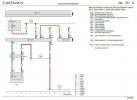
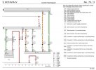
1. I've tried to map the official wiring diagram with your above notes, but I'm a bit confused about the wire connections for Connector T8y/Pin2 (from J1087 side assist second control unit) and connect T8x/Pin4(from J1086 side assist master control unit). Are they cross connected? Please find bellow the flow diagram.
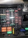
2. Based on the SK official documentation they changes the fuse used to SC44, but in the above instructions you connected the main power supply to S21. Even so, I've been thinking to use another existing spare fuse location, better and safe. In my case S22 is a good candidate(I need to check with a multimeter for 12V power) .
Is the S21 a constant power OR switched fuse?
What it's you opinion on this?
Fuse Panel:

 car-fuse.blogspot.com
Really appreciate your inputs.
Br,
DN
First of all, congratulations for your hard work and time to share with the community this kind of valuable informations.
I'm also eager for this retrofit on my car, SK Octavia Mk4 which hasn't been built with this feature.
I do have couple of questions related to the schematics.
1. I've tried to map the official wiring diagram with your above notes, but I'm a bit confused about the wire connections for Connector T8y/Pin2 (from J1087 side assist second control unit) and connect T8x/Pin4(from J1086 side assist master control unit). Are they cross connected? Please find bellow the flow diagram.
2. Based on the SK official documentation they changes the fuse used to SC44, but in the above instructions you connected the main power supply to S21. Even so, I've been thinking to use another existing spare fuse location, better and safe. In my case S22 is a good candidate(I need to check with a multimeter for 12V power) .
Is the S21 a constant power OR switched fuse?
What it's you opinion on this?
Fuse Panel:
2020 - 2022 Skoda Octavia Fuse Panel Diagram
2020 - 2022 Model Skoda Octavia Fuse Boxes
car-fuse.blogspot.com
Really appreciate your inputs.
Br,
DN
Attachments
-
 bsd_schematics1.JPG80.1 KB · Views: 74
 -
 bsd_schematics2.JPG106.9 KB · Views: 75
 -
 IMG-20240727-WA0000.jpg545.5 KB · Views: 70
Last edited:
Hello DN,Hello @mysticscalex,
First of all, congratulations for your hard work and time to share with the community this kind of valuable informations.
I'm also eager for this retrofit on my car, SK Octavia Mk4 which hasn't been built with this feature.
I do have couple of questions related to the schematics.
1. I've tried to map the official wiring diagram with your above notes, but I'm a bit confused about the wire connections for Connector T8y/Pin2 (from J1087 side assist second control unit) and connect T8x/Pin4(from J1086 side assist master control unit). Are they cross connected? Please find bellow the flow diagram.
2. Based on the SK official documentation they changes the fuse used to SC44, but in the above instructions you connected the main power supply to S21. Even so, I've been thinking to use another existing spare fuse location, better and safe. In my case S22 is a good candidate(I need to check with a multimeter for 12V power) .
Is the S21 a constant power OR switched fuse?
What it's you opinion on this?
Fuse Panel:
2020 - 2022 Skoda Octavia Fuse Panel Diagram
2020 - 2022 Model Skoda Octavia Fuse Boxes
Really appreciate your inputs.
Br,
DN
thanks for providing a good question with good source material.
1. The wiring diagram is same as mine, but digital ofcourse. If you look at the wiring diagram you see that the Pin 2 from your slave module goes to Pin 4 of Master module (right side of car). In the diagram is basically follows the same route as the Can Low wire which is above it, but they decided to draw it this way.
If you do make your own wiring harness, make sure you twist the CAN wires and make flexible but strong connections (for example Ground wires)
2. I understand you concern, but fuses are not so special. Almost all fuses are constant power, except a handful. The handful that are Key powered are on the same group (same line). Back in the day if you used to take key out, you could easily tell which was constant and which isn’t. Nowadays you have to let the car sleep (let it rest for couple minutes or lock the car) to turn off the KEY powered fuses. What I did was choose Fuse F17 (or F16, can’t remember) because SC21 (F21 was already used up.) this for me easier (still a pain in the butt) to access and looks more in line.
But for you Fuse 22 (SC22) is a good choice. If you lock the car while inside and check with multimeter it is 12v constant, which is needed.
once you disassemble the fuse box you will see that that line of fuses is connected to same strip of power and all of them are 12v constant.
In terms of Fuse, I used a 10A, as Kufatec advised this, but you can also use 7,5A like in wiring diagram.
Everything should be the same for Skoda, but the lights obviously and possibly the attachments behind the bumper.
A side note, for all that want to experiment/ install this.
-If you ever go to dealer for software related work (even service) tell them you added this retrofit. The modules are (if you did correctly) configured in VW server database and connected to the cars VIN, however, the car has a specific code that says what was installed in factory, and the retrofit isn’t added to the code.
So when doing software or diagnosis, VW dealer (ODIS) may not recognize that the car is added with said modules. (Mainly important for updates)
-Got this information from VW dealer themselves as advice!
Hello @mysticscalex,
Really appreciate your inputs on my questions.
Apologies if my concern is still newbie, but I still do find a difference between the official SK schematics and your wiring diagram:
a. inter CAN network connection from J1087 to J1086 is on 1->3 (odd) PINs for CAN Low, and 2 ->4 (even) PINs for CAN High
b. while in your above diagram picture the wires are cross-connected 1 & 4 and 2 & 3.
Can you please clarify?
Thank you.
Cheers
Sorry, just noticed I drew the wires incorrectly, can low goes from pin 1 to 3 and can high from pin 2 to 4, I accidentally connected can high to can low. Sorry for that. Just use the Skoda schematics and you are good.Hello @mysticscalex,
Really appreciate your inputs on my questions.
Apologies if my concern is still newbie, but I still do find a difference between the official SK schematics and your wiring diagram:
a. inter CAN network connection from J1087 to J1086 is on 1->3 (odd) PINs for CAN Low, and 2 ->4 (even) PINs for CAN High
b. while in your above diagram picture the wires are cross-connected 1 & 4 and 2 & 3.
Can you please clarify?
Thank you.
Cheers
Are you planning on making your own cable set or buying them?
Thank you for the clarification @mysticscalex.
To be honest I'm exploring all the variants/possibilities for this retrofit:
1. Chinese wiriness + mirror lamps + SK OEM Black mirror caps + VAG OEM modules & brackets
2. "home made" wiring harness + all the above
3. Kufatec set which is the most expensive option:

 kufatec.com
To be honest I'm exploring all the variants/possibilities for this retrofit:
1. Chinese wiriness + mirror lamps + SK OEM Black mirror caps + VAG OEM modules & brackets
2. "home made" wiring harness + all the above
3. Kufatec set which is the most expensive option:
Lane change assistant incl. rear traffic allert for Skoda Octavia NX
Complete set for retrofitting the lane change assistant (Side Assist) including rear traffic allert for Skoda Octavia NX
You dont need mirrorcaps on the Leon KL of its another brand is could be different. Golf 8 is different wiring voor de lights then the Leon for your info. So Skoda is more like the Golf wiring. You need to check that wiring diagram
Kufatac product does provide ease and is very good.Thank you for the clarification @mysticscalex.
To be honest I'm exploring all the variants/possibilities for this retrofit:
1. Chinese wiriness + mirror lamps + SK OEM Black mirror caps + VAG OEM modules & brackets
2. "home made" wiring harness + all the above
3. Kufatec set which is the most expensive option:
Lane change assistant incl. rear traffic allert for Skoda Octavia NX
Complete set for retrofitting the lane change assistant (Side Assist) including rear traffic allert for Skoda Octavia NX
AliExpress set can be fine, but if they mess up the cable connection it is a pain to find and fix it.
making it yourself is the most fun, but you need to keep in mind you need a lot of different connectors and cable. Also special connectors for the lights and the modules. After that you need to wire it correctly and make sure you have the connecting points like ground solid. So fun, but a lot of work.
in the end, it’s what your wallet allows, but choosing kufatec does give you reassurance that it is correctly installed.
and as Antera said, you obviously have the lights in the mirrors which is little bit extra work. You also need to check if the lights are 3 wires or 2. If 3 wires, then 1 is ground, other is power and the last one is LIN signal wire.
Thanks guys for your advises.
I've also checked the wiring diagram for VW Golf Mk8 and besides the lamps that are located in mirror caps like SK Octavia Mk4, they are 3 wires connection. The SK schematics is identical with the Seat Leon KL, by using 2 wires instead.
Still investigating all the variants/possibilities for this retrofit with the better reassurance that everything will just work and minimum cost.
Cheers
If you need you can send me a private message i have made wiring diagram for the various cars also for the Golf MK8. Idd a few retrofits on different cars
Last edited:
Hi @Antera,
Thank you for your offer, but the wirings are the things are worrying me less(I have experience on many retrofits but on different brand- Ford). The radars are the most sensitive parts, and the fact that ODIS-E is mandatory(which is not pretty common in my country due to it's cost, and available only on dealers) to do the software tricks (firmware rewrite if necessary, CP removal, calibration files,...).
Hi @mysticscalex,
I've tried to find a fuse that is completely power disconnected after the card goes to sleep, but I didn't find any. All the S1x and S4x fuses are +12V power supplied. I used the following trick to test: with a flat screwdriver I blocked the door latch in the closed position then I closed the card using the key (not with keyless touch button), moved the key far away from the car. I came back later after ~ 30-40mins, then with a multimeter I tested all the S1x and S4x fuses.
Am I missing something OR the there is nothing wrong with the constant power all the radar modules?
TIA
Fuse 21 is the fuse for Blind spot and is always active
if coded correct it will warn you with a warning sound on the speakers when opening door en traffic is comming from behind. That is why
if coded correct it will warn you with a warning sound on the speakers when opening door en traffic is comming from behind. That is why
Buonasera te dici che avendo già l'illuminazione interna è possibile adattarla se non ti chiedo troppo come bisognerebbe adattarla grazie milleAvendo già l'illuminazione interna avvolgente, è possibile adattarla trovando solo i radar e il cablaggio? Il cablaggio è lo stesso delle cugine Golf 8 e Audi A3 8y?
Similar threads
- Replies
- 2
- Views
- 3K
- Question
Model Year 24/25
Adding Blind Spot Detection to 2025 Cupra Formentor: Is it Possible?
- Replies
- 24
- Views
- 1K