• Guest would you be interested in CUPRA or SEAT valve caps? let us know in the poll

  • Welcome to our new sponsor Lecatona, a brand dedicated to enhancing performance for VAG group sports cars, including SEAT, Audi, Volkswagen and Škoda. Specializing in High Pressure Fuel Pump (HPFP) upgrades.

layout of boost vacuum pipes needed

nathal

Active Member
Oct 20, 2008
100
0
i have a limp problem on my toledo, which has being goin on for a while now, with alot of parts replaced. i removed the pipe running from actuator and it has left me no limp mode.

anyway, was thinking i better check the pipes are connected to the right valves as the previous owner could have altered these.

on my bulkhead i have anti shuuder valve, egr valve, and turbo boost valve, any help appreciated
 

Muttley

Catch that diesel!
Mar 17, 2006
4,987
31
North Kent
:cry:

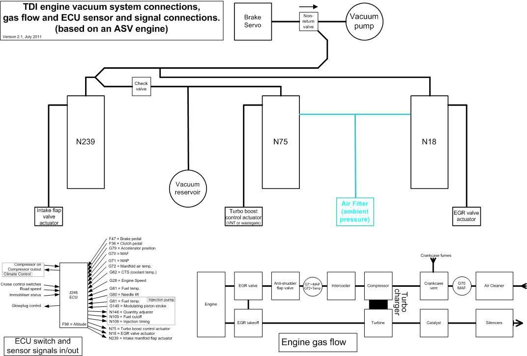
Your thread "Engine seized because of intercooler cleaning", post 35. My post. Where I gave you the diagram you are asking for here, one that doesn't exist in the manuals, one I drew myself.

This one

TDIvacsys.jpg
 

nathal

Active Member
Oct 20, 2008
100
0
great job, missed that one.

btw, do you know where i could get relacement tubing aswell
 

nathal

Active Member
Oct 20, 2008
100
0
hi muttley, could you help me check the check valve is right way round, as you look at engine, the valve is black on one side and white on other. on my car, the valve has the white side towards passenger side.

below is the n75. could you show me which pipe goes to top and bottom

http://www.tdiparts.com/catalog/popup_image.php?pID=447&osCsid=993250c4f27bfbdeb21a69e4710e1ca0

same for the n18
http://www.tdiparts.com/catalog/popup_image.php?pID=446

and same for n239, cant find pic

if i turn the check valve round, i have no limp mode.

does the problem sound like a boost leak
 

nathal

Active Member
Oct 20, 2008
100
0
http://img359.imageshack.us/img359/902/n2101272ml.jpg

1. Vacuum unit for shut-off valve
◆ For coolant circuit for fuel cooling
◆ Only vehicles up to 01.02
2. Exhaust gas recirculation valve (mechanical)
◆ Component part of intake connecting flange
◆ Can only be replaced together with intake connecting flange
3. Exhaust gas recirculation valve (N18)
4. Brake servo
5. Non-return valve
6. Tandem pump
◆ For fuel and vacuum supply
7. Cylinder head
8. Intake manifold
9. Intake manifold change-over vacuum unit
10. Intake manifold flap change-over valve(N239)
11. Air cleaner
12. Charge pressure control solenoid valve (N75)
13. Non-return valve
◆ White connection to charge pressure control solenoid valve item 12 and to vacuum reservoir
14. Vacuum reservoir
15. Charge air cooler
16. Pressure unit
◆ For charge pressure control
◆ Integral part of turbocharger cannot be replaced
17. Turbocharger

also found another diagram

this is the diagram for the AVF and AWX engines
 
Last edited:

Muttley

Catch that diesel!
Mar 17, 2006
4,987
31
North Kent
:headhurt:

The valves in those pictures are labelled!

VAC at the end
OUT in the middle (control output)
the one that's left over, the atmospheric connection to the airbox, goes on the connection closest to the electrical plug.

you wrote

hi muttley, could you help me check the check valve is right way round, as you look at engine, the valve is black on one side and white on other. on my car, the valve has the white side towards passenger side.

in my UK spec, right-hand-drive car, the check valve is mounted white-side towards the vacuum reservoir and N75 valve, which is towards the nearside i.e. the passenger side.

if i turn the check valve round, i have no limp mode.

probably means you're isolating the N75 from vacuum and have no turbo actuation either.

does the problem sound like a boost leak

Not to me, no.


AVF and AWX are 96kW PD engines, quite different from our non-PD VNT turbo engines.
 

nathal

Active Member
Oct 20, 2008
100
0
well, problem is cured at high revs.

no more limp mode, turbo's out to the max

i get an odd limp, when at low revs when car is cold.

i fixed the problem, by spraying CONTACT CLEANER on all the electrical plugs and round maf and plug.
 

nathal

Active Member
Oct 20, 2008
100
0
spoke to soon, problem isnt fixed.

muttley, thanks for the diagram, discored after overlooking the first time, that my pipes werent in the right place.
there are two sizes of pipes on car, small ones and larger ones,(one from airbox to n75) what size are these

also should my pipe to turbo actuator be the small one or the large one.
 

nathal

Active Member
Oct 20, 2008
100
0
Engine Bay Hoses

Normally replaced by silicone hoses

Vacuum hoses - 3 or 4mm ID - personal preference
DV Connection - 25mm on both sides
PCV pipe work - 19mm
Elbow off side of manifold to brake servo - 90degree 12mm (check)
MAF elbow - 45degree 70mm elbow
Crankcase breather elbow - 90 degree 19mm
Majority of coolant lines are 19mm
Top header tank connection 8mm
Lower Header tank - 15mm (check)
N75 connections - 8mm


got the sizes
 
Lecatona HPFP (High-pressure Fuel Pump Upgrades)