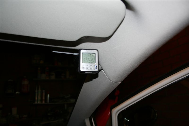
I just hardwired my TomTom sat nav and thought the info my useful for others.
1. Solder red and black wire (use a decent gauge wire 16/0.2 or similar) to power adaptor - take care not to push on the contacts when soldering as the plastic gets very soft when heated. Use a hot bit (I know they are all hot, but some are hotter than others!), tin the contacts first, tin the wire ends, get a nice bit of solder on the iron tip and let the heat do the work. Once the solder has set cool it with the wet iron sponge or the like (this will harden the plastic quickly).

2. Prepare the terminals as follows, take a 0.25 inch blade and trim it down to a similar size. This will fit in spare connection on the fuse panel. The one I have used is ignition switched. The ring (5mm hole) is used for the ground connection and is secured under the fuse panel and reatained by the bolt - torx bit required here.


3. Connect ground and positive connections as per photograph. Ensure security of each!! I haven't used an inline fuse holder as the power adaptor has a 2 amp fuse fitted - I may well fit one in hindsight, 20mm fuse rated at 2 amp. I'm not sure if the built in one protects the supply or the output, I'd expect it to be the supply...but better safe than sorry!


4. Tie up power adaptor - MIND CABLES BEHIND METALWORK, IF YOU TIE UP AND CATCH THESE AS WELL YOU MAY WELL PULL THEM OFF THE LIGHT SWITCH OR DAMAGE THEM ANOTHER WAY. ENSURE CABLE TIE DOES NOT GO AROUND THEM AS WELL.

5. Tie up excess cable.

6. Finished installation.


Et voila!
Any questions just PM me.
1. Solder red and black wire (use a decent gauge wire 16/0.2 or similar) to power adaptor - take care not to push on the contacts when soldering as the plastic gets very soft when heated. Use a hot bit (I know they are all hot, but some are hotter than others!), tin the contacts first, tin the wire ends, get a nice bit of solder on the iron tip and let the heat do the work. Once the solder has set cool it with the wet iron sponge or the like (this will harden the plastic quickly).

2. Prepare the terminals as follows, take a 0.25 inch blade and trim it down to a similar size. This will fit in spare connection on the fuse panel. The one I have used is ignition switched. The ring (5mm hole) is used for the ground connection and is secured under the fuse panel and reatained by the bolt - torx bit required here.


3. Connect ground and positive connections as per photograph. Ensure security of each!! I haven't used an inline fuse holder as the power adaptor has a 2 amp fuse fitted - I may well fit one in hindsight, 20mm fuse rated at 2 amp. I'm not sure if the built in one protects the supply or the output, I'd expect it to be the supply...but better safe than sorry!


4. Tie up power adaptor - MIND CABLES BEHIND METALWORK, IF YOU TIE UP AND CATCH THESE AS WELL YOU MAY WELL PULL THEM OFF THE LIGHT SWITCH OR DAMAGE THEM ANOTHER WAY. ENSURE CABLE TIE DOES NOT GO AROUND THEM AS WELL.

5. Tie up excess cable.

6. Finished installation.


Et voila!

Any questions just PM me.
Last edited:


